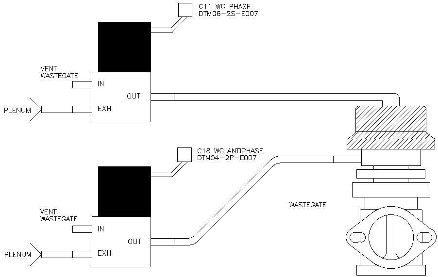
Two three port 12VDc solenoids are used
(MAC or Humphrey). One for Phase and the other for Antiphase. Be sure
they have a large enough flow coefficient
(Cv) and that they have 1/4" NPT ports. You should reverse the
connector scheme on one of the solenoids so they cannot be mixed up. In
the example above one solenoid uses pins and the other sockets.
Use two separate points (2X) for the pressure (boost) supply as
pressure is always, somewhere, "vented off". In theory it is possible
for
the supply to be vented rather than directed to the correct
solenoid/wastegate port, especially around a 50% duty cycle. Lines can
be
as small as AN3 or, more typically, AN4 (1/4").
The solenoids are plumbed so that, when the solenoids are "off", the
boost goes directly to the wastegate's middle and top ports. When the
solenoids are "on" the boost pressure from the turbo is blocked and the
wastegate's middle and top ports are vented to air. Varying the on/off
duty cycle allows control between fully shut and fully open.
The solenoids are typically programmed to cycle at a constant 20Hz and
only their
duty cycle varies, from 0-100%. Higher Hz, say up to 35Hz can offer a
smoother control of the valve (not essentially the boost) but a smaller
operating window and less response. 20Hz is a good workable start
point. Solenoids do not have a good resolution
up to 10% or above 90% duty cycles. By programming the duty cycles in
an
opposing fashion and varying the pressure above and
below the wastegate's diaphragm, very precise boost control can be
achieved.
Three Examples:
1. At the leftmost of the 21 programmed entries the Phase is Zero and
the Antiphase is 100. Since the Phase Solenoid is at Zero duty cycle
the top of the wastegate receives full boost. The Antiphase
solenoid is 100% so it vents the area beneath the wastegate diaphragm.
The result is the wastegate valve is pushed shut. Maximum boost.
2. At the rightmost of the 21 programmed entries the Phase is 100 and
the Antiphase is Zero. Since the Phase Solenoid is
100% the top of the wastegate is vented to air. The Antiphase Solenoid
is at Zero duty cycle so the area beneath the wastegate diaphragm
receives full boost. The result is the wastegate valve is pushed fully
open. No boost.
3. At the 11th entry both Phase and Antiphase are both at 50% duty
cycles. In theory there is only spring pressure minus the backpressure
effect on the valve area applied to the wastegate. Boost is dependant
on the valve area and spring seat pressure.
Facts / Comments:
1. Light wastegate springs are called for. In theory you do not need a
spring but in reality you need a light spring to supply a force higher
than applied to the wastegate's valve by the exhaust backpressure.
People make the mistake of running
heavy springs to get turbo response and boost, but you do not need them
and you cannot control them.
2. It is very important to control the boost with correct wastegate
size and spring pressure. Essentially, when the pressure target is
correct, the wastegate should never be closed at any RPM, especially at
high RPM and the wastegate duty cycle should be somewhere around 70%.
If this is not achievable either the wastegate/spring combination is
wrong or the turbo sizing is not correct.
3. PID Programming Advice: Introduce Proportional control first as
Proportional is for immediate response. Intergral and Derivative can be
zeroed out initially. Intergral can be introduced to modify error
correction versus time, but be careful of Integral windup as it is
against time. Lastly, Derivative is for fine tuning.
4. Braided stainless AN3 / AN4 boost lines are really fluid lines and
not air lines and can abrade surfaces they are in contact with. EFI
hoses can be used and are rated to about 275F. We use reinforced 1/4"
silicone hoses that are rated to 500F. Silicone hose that is not
reinforced is easily torn.


