![]()
![]()
Camshafts

Things that go "Bump in the Night"
Cams are the secret ingredient in the internal combustion soup...bumpsticks instead of breadsticks! More dangerous sounding names have been assigned to cams than any other part you'll find in your motor, further compounding their mystery by giving them personalities. Who would dare to ask the "Dominatrix" that lifts your valves what her stats are? We've put together a calculator that will tell you what your cam's lobe centers and durations are to shed some light on this mysterious subject.
Open and Shut Case
When does that valve open anyway? Well, to determine this we have to put dial indicator on the valve to see when it lifts off of its closed position...for both the inlet and exhaust valves. We need a reference point for this and we'll choose the engine's Top Dead Center (TDC) on the particular cylinder we are measuring. TDC is the point were the piston is as close to the cylinder head as possible and the place in the engine's rotation where both inlet and exhaust valves are closed. You'll know they are closed if both pushrods, in the case of a 2 valve motor, are "loose" and not under tension.
Where the Hell is TDC ?
How do we know exactly where this TDC point is anyway? Well, to do this we need to put a circular degree wheel on the end of the crankshaft that has 360 marks, one for each degree of crankshaft movement as well as marks for TDC (zero degrees) and BDC (180 degrees). BDC is bottom dead center, where the piston is as far away from the cylinder head as possible. A piece of wire can be manipulated into place to align up with the TDC mark (zero degrees).
The best way to find the exact TDC is to use an adjustable mechanical stop that screws into the the spark plug hole. Put the motor at a point near to where you think TDC is i.e. both valves are closed and screw in the mechanical TDC stop. Gently screw in the adjustable portion of the stop till it contacts the top of the piston and lock it down. From this point you can gently turn the motor clockwise and counterclockwise until it gently hits this stop. Note these two degree figures, split the difference, and put the wire on the new TDC point (zero degrees). Rotate the engine cw and ccw again to verify that the mechanical stop hits the piston the same number of degrees before and after TDC (BTDC, ATDC). Adjust the wire you've arranged as a pointer, if necessary, to point to the TDC mark. You've now found TDC! Ground zero in your search for truth.
No Tower of Babel
To insure we all speak the same language we have to agree on the same starting point. In this case it's how far the valve lifts before we start writing down those degrees. The industry standard is when the valve lifts .050 inches (fifty thousandths) off it's seated position. The idea in this is that we will start at an agreed on point where there is "measurable" flow, the assumption being that there is no meaningful flow in the first .050" of valve lift. So, get the cylinder to TDC, making sure both valves are closed and set a dial indicator on either your inlet or exhaust valve. Set the indicator dial to zero and slowly rotate the engine and note the degrees at which the valve hits this magic .050" point. This will be .050" of lift after it opens and .050" before it closes.
TDC, BDC, BTDC, ATDC, BBDC, ABDC, Hike!


Since we all speak the same language on this monumental project we know that BTDC is "before top dead center" and ATDC is "after top dead center". BBDC is "before bottom dead center" and logically ABDC is "after bottom dead center".
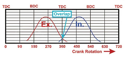
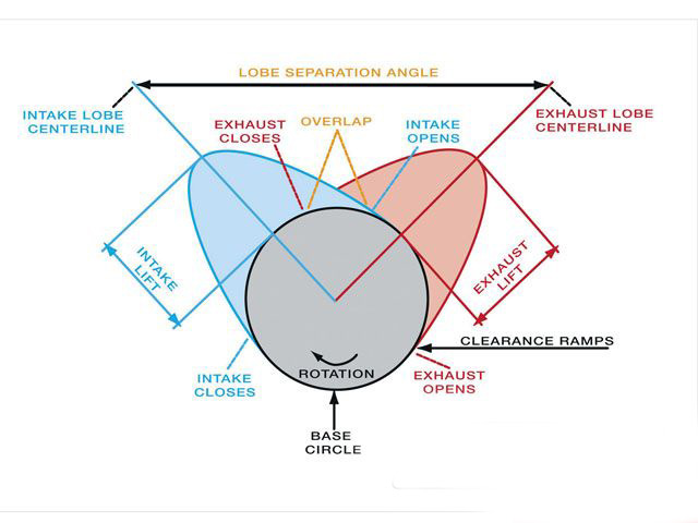
When you write down the figures you have to add these acronyms to your degree figures. Inlet cams will generally open x degrees BTDC and close x degrees ABDC. Exhaust cams will generally open x degrees BBDC and close x degrees ATDC.
Once you've got your figures at .050" lift for both the inlet and exhaust valves you can plug these figures into the calculator to get information about your cam's duration and installed centerlines.
Sample of Harley-Davidson TC Specs
|
Manufacturer/Product
|
Intake Open BTDC
|
Intake Close ABDC
|
Exhaust Open BBDC
|
Exhaust Close ATDC
|
|
Andrews TW37
|
12
|
42
|
48
|
12
|
|
Andrews TW64G
|
30
|
62
|
68
|
32
|
|
Crane HTC-290-2
|
18
|
42
|
46
|
22
|
|
Crane HTC-304-2
|
25
|
49
|
56
|
24
|
|
Leinweber RE-T3S
|
17
|
41
|
51
|
11
|
|
Leinweber RE-T5S
|
24
|
40
|
56
|
12
|
|
Red Shift 577TC
|
25
|
46
|
53
|
22
|
|
Red Shift 657TC
|
21
|
52
|
58
|
16
|
|
S&S 640G
|
25
|
60
|
65
|
25
|
|
S&S 675G
|
25
|
64
|
70
|
25
|
|
Screaming Eagle SE-264
|
24
|
60
|
60
|
22
|
Sample of Harley-Davidson EVO Specs
|
Manufacturer/Product
|
Intake Open BTDC
|
Intake Close ABDC
|
Exhaust Open BBDC
|
Exhaust Close ATDC
|
|
Andrews EV51
|
28
|
44
|
54
|
22
|
|
Andrews EV84
|
32
|
64
|
70
|
30
|
|
Crane H290
|
17
|
43
|
45
|
23
|
|
Crane H310
|
23
|
63
|
68
|
28
|
|
Leinweber E-4
|
49
|
74
|
76
|
39
|
|
Leinweber E-9
|
53
|
81
|
86
|
38
|
|
Red Shift 575
|
25
|
54
|
63
|
18
|
|
Red Shift 656
|
28
|
52
|
52
|
26
|
|
S&S 600
|
20
|
55
|
60
|
20
|
|
S&S 631
|
34
|
61
|
66
|
29
|
|
Screaming Eagle SE-60
|
26
|
56
|
61
|
24
|