really big verson
color big verson
Hawkworks.net main page
Manual main index
| SERVICE INFORMATION | 16-1 |
| TROUBLESHOOTING | 16-2 |
| IGNITION SYSTEM INSPECTION | 16-3 |
| IGNITION COIL | 16-3 |
| PULSE GENERATOR | 16-4 |
| IGNITION TIMING | 16-4 |
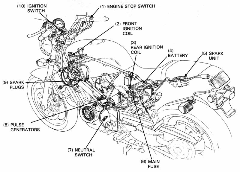
Spark plug
| NGK | ND | |
|---|---|---|
| Standard | DPR8EA-9 | X24EPR-U9 |
| For cold climate (below 5°C/41°F) | DPR7EA-9 | X22EPR-U9 |
| For extended high-speed riding | DPR9EA-9 | X27EPR-U9 |
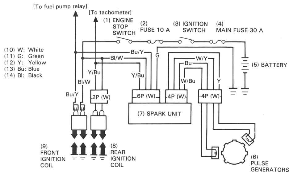
Ignition system
| ITEM | STANDARDS | ||
|---|---|---|---|
| Ignition timing | Initial (F mark) | 10° BTDC/idle | |
| Ignition coil resistance (20°C/68°F) | Primary circuit | 2.2-2.6 Ω | |
| Secondary circuit | With plug wire | 30-36 kΩ | |
| Without plug wire | 20-25 kΩ | ||
| Pulse generator coil resistance (20°C/68°F) | 450-550 Ω | ||
| Firing order | Front - (232°) - Rear (488°) - Front | ||
| Tester | |
| 07411—0020000 | (KOWA Digital type) |
| KS—AHM—32—003 | (KOWA Digital type; USA only) |
| 07308—0020001 | (SANWA Analogue type) |
| TH—5H | (KOWA Analogue type) |
No spark at one spark plug
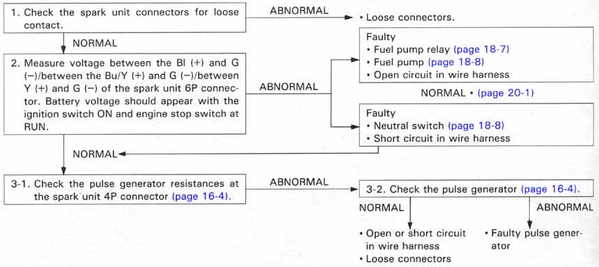
No spark at all plugs
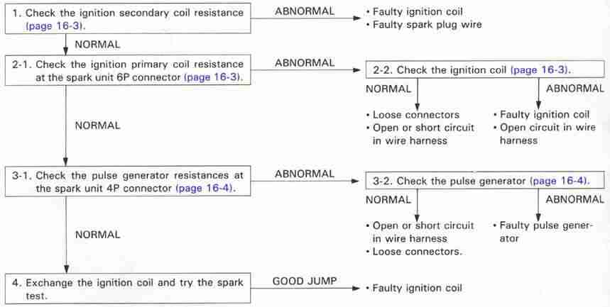
No spark at either spark group (Front or Rear) - (CHECK WRONG SPARK GROUP)
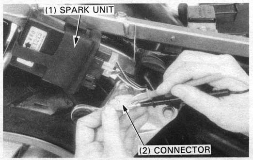
Remove the seat and rear cowling (page 13-25).
Measure the data between connector terminals using the following chart.
| ITEM | TERMINALS | STANDARD (20° C/68°F) |
|---|---|---|
| Ignition primary coil | Y and Bl/W (Rear) Bu/Y and Bl/W (Front) | 2.2-2.6 Ω |
| DC power supply circuit line | Bl (+) and G (-), Bu/Y (+) and G (-), Y (+) and G (-) with the ignition switch "ON" and the engine stop switch "RUN" | Battery voltage should come |
| ITEM | TERMINALS | STANDARD (20° C/68°F) |
|---|---|---|
| Pulse generator coil | W/Y and Y (Front) W/Bu and Bu (Rear) | 450-550 Ω. |
| Each terminal and body ground | NO CONTINUITY |
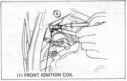
Remove the seat and fuel tank (page 13-25).
Measure the primary coil resistance of the front and rear ignition coils.
PRIMARY COIL RESISTANCE:
STANDARD: 2.2 - 2.6 Ω (20°C/68°F)
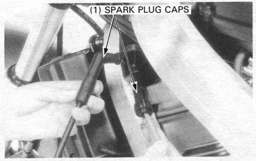
STANDARD: 30-36 kΩ (20°C/68°F)
If the resistance is out of range, remove the spark plug caps and measure the resistance between the secondary coil terminals.
STANDARD: 20-25 kΩ (20°C/68°F)
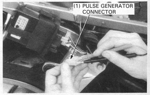
Remove the seat and rear cowling (page 13-25).
Disconnect the pulse generator 4P connector (WHITE).
Measure the resistances between the white/yellow and yellow
wires (front pulse generator) and white/blue and blue wires
(rear pulse generator)
STANDARD: 450 - 550 Ω (20°C/68°F)
For pulse generator replacement, refer to section 7. <– Corrected ref.
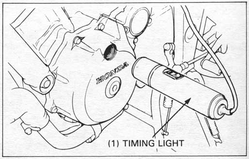
Warm up the engine to operating temperature.
Remove the timing inspection hole cap on the left crankcase cover.
Connect the timing light to the front spark plug wire.
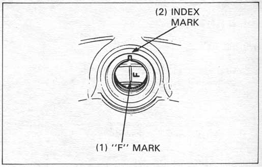
The timing is correct if the "F" mark aligns with the index mark on the right crankcase cover at idle for each cylinder.
Raise the engine rpm and the "F" mark should begin to rotate counterclockwise for each cylinder.
If the ignition timing is incorrect, make a ignition system inspection (page 16-3) and replace any faulty parts.